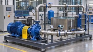

Start data center liquid cooling pump selection with the circuit the pump serves. In a coolant distribution unit (CDU), the facility side and the technology cooling side can have different fluids, temperatures and pressure limits. A nominal flow value without its loop boundary and pressure-drop assumptions is difficult to compare across suppliers.
The Open Compute Project’s CDU work covers integration of liquid distribution into data center facilities. Use the applicable project documents and equipment specifications when turning the checklist below into an RFQ.
1. Define the loop and its operating cases
Record the fluid type and concentration, operating temperature range, design flow and expected minimum and maximum flows. Separate the pressure drop of the heat exchanger, filters, hoses, manifolds and equipment on the side served by the pump. Ask equipment suppliers to state the flow and fluid conditions behind each pressure-drop figure.
- Normal load: record the active racks, flow and control setpoint.
- Peak load: include the equipment operating together and the specified fouling or filter allowance.
- Reduced load: check what the pump and controller do when many branches reduce flow.
- Standby takeover: define the minimum required flow while one unit is unavailable.
2. Compare the pump curve to each duty point
Plot expected duty points against the candidate curves at the applicable speeds and fluid conditions. Check the manufacturer’s permitted operating range, motor loading and any limits on suction pressure. Use the NPSH checklist to document assumptions behind the suction assessment, then compare centrifugal pump curves across candidates.
3. Specify redundancy and the controls sequence
Document what triggers standby startup and whether the standby unit can meet the required degraded-mode flow. For parallel pumps, compare the one-pump and combined curves against the same system scenarios. Include isolation and check-valve assumptions, sensor locations, alarm thresholds and the expected response when a sensor or drive becomes unavailable. See the parallel pump selection guide for the curve comparison.
4. Request evidence you can compare
| Supplier deliverable | What to check |
|---|---|
| Selection sheet | Fluid, temperature, speed, flow, head and expected input power at the stated duties |
| Operating envelope | Minimum flow, pressure limits, materials compatibility and service access |
| Controls description | Lead/lag sequence, alarms and the behaviour during a planned changeover |
| Test plan | Acceptance criteria, measurement points and the runs needed to verify rated and standby operation |
For a supplier review or selection software demonstration, bring the duty table and the loop schematic. The Velotech pump selection software demo checklist outlines the information that makes a comparison repeatable.